Different Tests On Induction Motors
Tests On Induction Motors
1. Hummer Test
Due to different reasons the stator coil/coils get shorted.
Indications of shorted coil:
- Stator takes high current than normal current
- Smelling sensation due to burning of insulation.
- May produce disconnection.
Hummer test is suitable for locating shorted coil in stator. A portable hummer is moved over the stator coils. An induce colour producing humming sound is heard when the hummer comes above the shorted coil. If a light weight back-saw blade is put over the shorted coil the blade vibrates.
2. Earth Fault
See the following testing circuit to locate earthed stator coil.
Three terminals of stator coil are connected together and variable resistance R and an
ammeter is connected along with the wire connected to the earthing system.
 |
| Earth Fault Test Circuit Diagram |
By making the switch of single phase A.C. supply "ON' and adjusting the variable resistance, sufficient current is passed which produce heating.
As shown in the diagram the stator frame is placed on the wooden plank.
On passing current, the smoke is produced in the faulty coil and hence it is detected. The faulty coil is discarded.
Starting Test (Tests Before Commissioning)
Before carrying out the tests as per ISI standards some primary tests are carried out at the site by external and superficial examination of the machine as follows:
(A) Mechanical Tests
1)Read the data printed on the name plate and check the same for the machine.
2) See that all the parts are in position and all the accessories are available and no parts are missing. See also the compactness of the machine.
3)Fit-in the parts which are supplied separately along with the main machine.
4)See that there is no damage during transport, tighten the nut bolts, screws etc. if
loose.
5)Check the alignment of shaft, coupling etc, tightness of terminal connections.
6) Check the condition of bearings by moving the shaft manually and provide a proper lubrication/greecing.
7) Check the clearance between stationary and rotating parts as per the specifications.
8) Check the terminal connections and tighten them if required.
9) Bearings and lubrication for free and smoothness of rotating parts.
10) Check the spring tension, brush position and shape of brushes. Check also commutator surface and commutator risers.
(B) Electrical tests
1)Check winding resistance as per given values.
2)Check insulation resistance between windings, between windings and corse.
and with external body.
3) Reduced voltage run test.
4) Check cooling system electrical.
5) Checking earthing provision.
After these primary tests the necessary ISI tests are carried out.
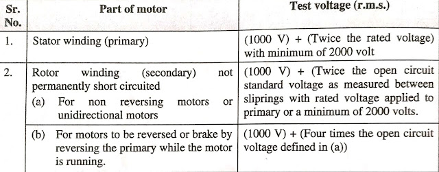
H.V. Test
In this test specified voltages is applied between various windings and earth. This test should be carried out together with the insulation resistance test at manufacturer's works Generally high voltage test is applied only if insulation resistance is less than the specified limit.
Method of testing
The test shall be made with alternating voltage of any convenient frequency between 40 Hz to 60 Hz. The test voltage should be of sine waveform (approximately).
Duration
The test is started by applying 1/3 of the test voltage and then voltage is increased to full-test voltage in accordance with the Table.
 |
| HV Test Voltage Table |


0 Comments