Basic Terminology Of Power Quality Part-1
Basic Terminology Of Power Quality Part 1
1. Recovery Time
2. Ride Through
3. Sag
4. Surge
5. Swell
6. Transient
7. Oscillatory Transient
8. Overvoltage
9. DC Offset
10. Common Mode Voltage
11. Dropout
12. Dropout Voltage
13. Ground Window
14. Harmonic Number
15. Islanding
16. Long Duration Variation
Basic Terminology Of Power Quality Part 2
1. Harmonics
Harmonies are sinusoidal voltage/current having frequencies that are integer multiple of fundamental frequency. Harmonics in the system can
- Make relays maloperate
- Increase loss in capacitances, noises
- Telephonic cross talks
- Can cause increase in resonance.
2. Inter Harmonics
The voltage or the current that is not the multiples of power frequencies are called inter harmonics.
It is caused mainly due to non linear loads which cause overheating of the equipment. By using harmonic filters this can be eliminated.
3. Harmonic Distortion
Presence of higher harmonics makes waveform distorted and causes fundamental waveform distorted.
 |
| Waveform Of Harmonic Distortion |
4. Immunity (Or Disturbance)
The capability of the device to execute without any system degradation in the presence of electromagnetic disturbance is called as immunity.
5. Impulse
6. Isolation
It is the separation of one system from the other system from the undesired influences.
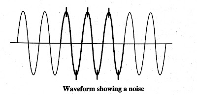
7. Noise
The unnecessary electrical signals that produce unwanted disturbances in the circuits are called as noise.
 |
| Waveform Of Noise |
8. Nominal Voltage
9.Inrush
Large current that is drawn when the machine is initially turned ON.
10. Interruption
An Interruption is defined as decrease in the supply voltage or load current less than the seconds or in other words it the loss of the voltage of the current or voltage for a complete time period.
11. Linear Loads
In steady state operation, if voltage and current are same as sinusoidal waveform then called linear loads. Linear loads do not have harmonics in them.
12. Non-Linear Loads
13. Notch
14. Power Disturbance
It is the divergence from the fundamental value of the input AC characteristics.
15. Periodic
16. Power Factor
Basic Terminology Of Power Quality Part 3
Basic Terminology Of Power Quality Part 3
1. Bonding
Bonding is the link of two or more conductive objects which are interconnected to one another by means of a conductor.
Bonding is done primarily for two reasons:
- To provide minimal of negligible voltage difference between the bonded parts.
- To ensure that, faults incurred can be safely moved to ground or other grids.
2. Grounding
Grounding, also referred to as "earthing", is a type of bonding where one or more conductive objects are connected to the ground by means of a conductor. In Fig. , equipment 1 and equipment 2 are connected by means of a thin wire and they are then connected to the ground.
(Figure)
3. Capacitance
The property of the circuit characterised by a two parallel plates which are separated by a dielectric medium and expressed in farad (F).
In other words, it is the means by which the energy can couple from one electric circuit to the other.
4. Coupling
The process by which electrical energy from one circuit is transferred to other circuit that are not connected electrically is called as coupling.
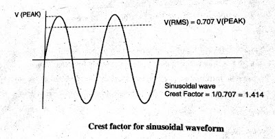
5. Crest Factor
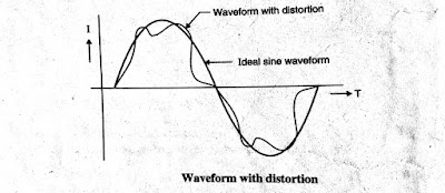
6. Distortion
 |
| Waveform with Distortion |
Distortion created in the waveform may cause waveform deformation as well as phase shift.
7. Distortion Factor
It is the relation between the RMS value of the harmonic content of a periodic waveform to the RMS value of the periodic wave and usually expressed as a percent.
8. Form Factor
It is the ratio of RMS value to the peak value of the periodic waveform.
It represents the deviation of the system waveform.
9. Flicker
It the visible change due to rapid fluctuations in the voltage of the power supply.
Flicker is due to a modulating low frequency disturbing voltage.
The frequency range visible to the human eye is about 1-30 Hz.
10. Frequency
Number of complete cycle in the periodic waveform and measured in hertz (Hz).
11. Ground Electrode
It is the body of the conductor that has contact with the earth for providing grounding to the network.
12. Ground Grid
13. Ground Loop
All the ground point should go through one common ground point
To isolate the source from ground
14. Ground Ring
The loop surrounding the structure or which is in straight contact with ground is called the ground ring.
The depth of the ground ring should be more than 2.5ft below the surface of the earth.
15. Grounding
A conductor, by which the electrical circuit or the equipment is connected to the earth or to some conducting body. Grounding is primarily done for two reasons:
Grounding the metal conductor protects any person coming in direct contact, if fault occurs.
It also allows the faulty current, to the earth or ground plane.


0 Comments